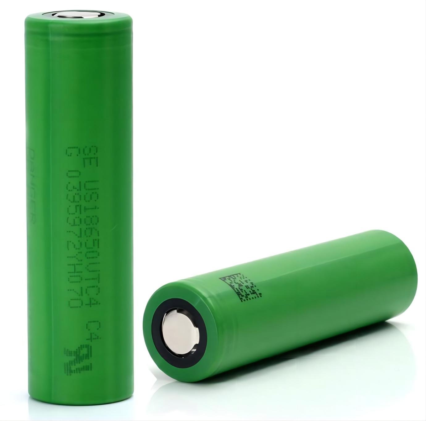
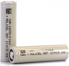
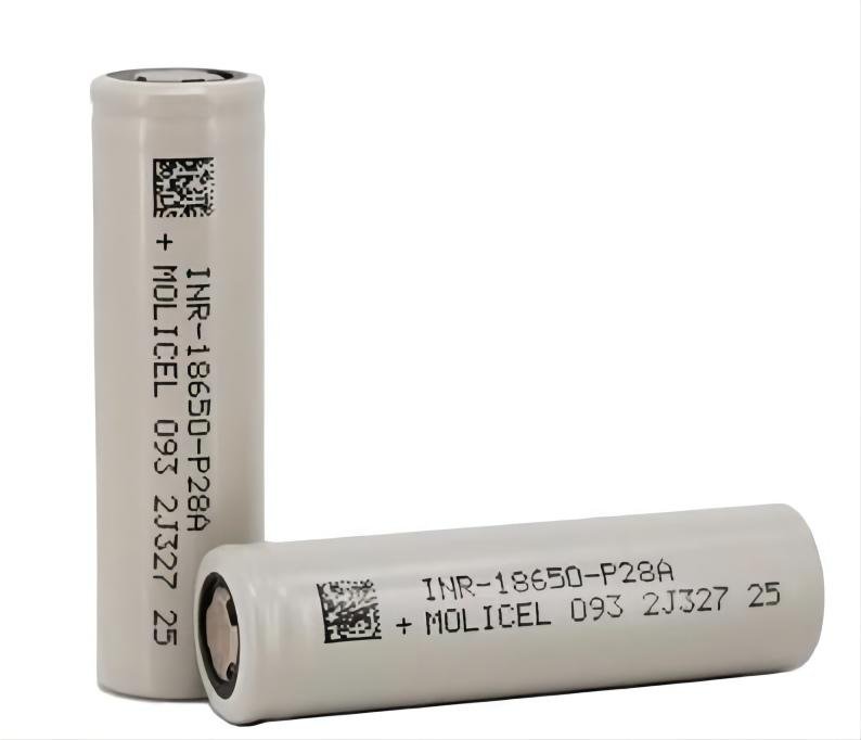
3.6V 3500mAh Molicel INR-18650-P35A
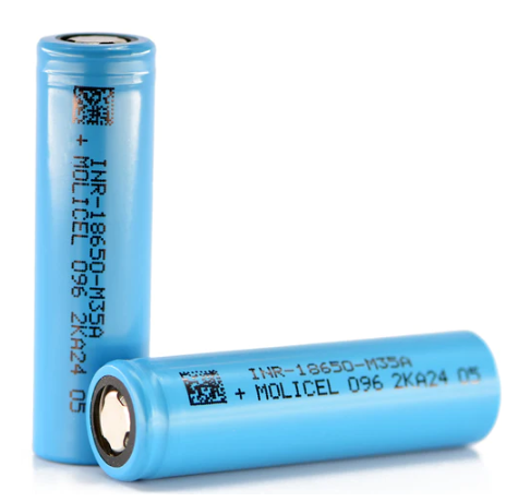
Molicel INR-18650-M35A–10A
The Molicel INR-18650-M35A cell comes up with a typical capacity of 3500mAh, the nominal voltage of 3.6V. This is an absolutely excellent cell for anyone seeking high performance 18650 cells.
HIGHLIGHTS OF Molicel INR-18650-M35A
Typical capacity: 3500mAh
Minimum capacity: 3350mAh
Nominal voltage: 3.6V
Standard charge current: 1.7A
Maximum charge current: 1.7A
Discharge cut-off voltage: 2.5V
Charge cut-off voltage: 4.2V
Maximum discharge current: 10A
Energy Density Volumetric: 700 Wh/l
Energy Density Gravimetric: 250 Wh/kg
APPLICATION: E-bike, E-scooter, EV, Medium power application
FEATURES:
1.High Energy Density
2.Excellent Low & High Temperature Perfomance (-30°C ~ 45°C)
3.Highly Safe & Stable
4.Long Cycle Life
5.Great Long Term Storage Characteristics
APPEARANCE
Shape: Cylindrical
Can : Steel
Diameter : 18.6 mm (Max)
Height : 65.2 mm (Max)
Weight: 48.0 g (Max)

Cell Date Code: YMDDSS
Y: indicates calendar year, 9=2009, A=2010, B=2011, C=2012, D=2013,
E=2014, F=2015, G=2016 etc.
M: indicates calendar month, 1~9, 10=A, 11=B, 12=C
AD: indicates calendar date of a month, 01~31
AS: indicates the sequence number in a day, 01, 02, etc


Nominal Specification of Molicel INR-18650-M35A
| ltems | Specifications | Remarks | |
|---|---|---|---|
| Rated charge | Limiting 1.7A and constant 4.2V charge for 2.5h or 50mA at 23 °C. | ||
| Rated discharge | Constant 0.68A discharge until 2.5V at 23°C | ||
| Rated capacity | 3.35Ah (Typical) 3.45Ah (Minimum) | Rated discharge capacity after rated charge. | |
| Nominal voltage | 3.6V | Mean voltage during rated discharge afterrated charge. | |
| Shipping voltage | ≥3.45V | Nominal approximate state of charge ≤ 30%. | |
| Internal resistance | ≤35mΩ | Fresh cell measured by AC impedance at1kHz | |
| End of charge voltage | 4.20±0.05V | - | |
| End of discharge voltage | 2.5V | Discharge voltage for determination of ratedcapacity. | |
| Charging time | 150 min | Rated charge. | |
| Maximum chargingcurrent | 1.7A | - | |
| Maximum dischargingcurrent | 10A | - | |
| Operatingtemperature | Charging | 0~60℃ | - |
| Discharging | -40~60℃ | - | |
| Storage temperature forshipping cell | <35℃ | Recommended temperature less than 23℃ for long term storage. | |
| Shelf life | 1 year | - | |
Performance
Standard Test Conditions
1.) Tolerance on temperatures is ±2 ℃.All tests performed at a relative humidity between 45% and 85% unless noted otherwise.
2.) 3 hours minimum soak time at specified temperature prior to discharging.
3.) The accuracy of measuring equipment (voltmeter and ammeter, etc.) shall be higher than class 0.5.
4.) 1.7A cycling: 1.7A charge to 4.2V for 100mA and 1.7A discharge to 2.5V, rest 10 minutes between discharge and charge.
5.) 3.4A cycling: 1.7A charge to 4.2V for 100mA and 3.4A discharge to 2.5V, rest 10 minutes between discharge and charge.
6.) 6.0A cycling: 1.7A charge to 4.2V for 100mA and 6.0A discharge to 2.5V, rest 10 minutes between discharge and charge.
7.) For incoming inspection purpose, the cells should be used in the tests within one week of receipt at customer.
Electrical Performance
| Item | Condition | Criterion | Test Method | ||
|---|---|---|---|---|---|
| 1 | 23℃ 1.7A | C500 | ≥ 70% | Per 5.1.4, 1.7A cycling at 23℃ to 500 cycles. The %=(Ah/3.30)*100% | |
| 2 | 23℃ 3.4A | C500 | ≥ 70% | Per 5.1.5, 3.4A cycling at 23℃ to 500 cycles. The %=(Ah/3.30)*100% | |
| 3 | 23℃ 6.0A | C500 | ≥ 60% | Per 5.1.4, 6.0A cycling at 23℃ to 500 cycles. The %=(Ah/3.30)*100% | |
Cycle Life
| Item | Condition | Criterion | Test Method | ||
|---|---|---|---|---|---|
| 1 | 23℃ 1.7A | C500 | ≥ 70% | Per 5.1.4, 1.7A cycling at 23℃ to 500 cycles. The %=(Ah/3.30)*100% | |
| 2 | 23℃ 3.4A | C500 | ≥ 70% | Per 5.1.5, 3.4A cycling at 23℃ to 500 cycles. The %=(Ah/3.30)*100% | |
| 3 | 23℃ 6.0A | C500 | ≥ 60% | Per 5.1.4, 6.0A cycling at 23℃ to 500 cycles. The %=(Ah/3.30)*100% | |
Storage Performance (SOC: State of Charge)
| ltem | Condition | Capacity Retention | Test Method | |
|---|---|---|---|---|
| 1 | 23℃ 1 month | 30%SOC | ≥25% | After storage,rated discharge and ratedcharge for two cycles. The retentioncapacity (Ah) is defined at 1st discharge after storage. The %=(Ah/3.35)x 100% |
| 2 | 23℃ 3 months | 30%SOC | ≥20% | |
| 3 | 23℃ 6 months | 30%SOC | ≥15% | |
PRECAUTIONS FOR USING LITHIUM ION RECHARGEABLE CELL
The precautions described below are important to assure the performance and safety of designed pack. Mishandling may cause cell leakage, heat, smoke, explosion or fire. Please follow instructions carefully.
Intended Use
Cordless screw driver, Cordless drill/driver, Cordless impact driver, Cordless tubing cutter, Cordless angle grinder, Cordless polisher/waxer, Power tool, Electrical vehicle, PHEV.
Handling Precautions
Charging
The lithium ion rechargeable cell is to be charged by “constant current/constant voltage” method. The lithium ion cell is charged at a constant current (CC Mode) until the cell voltage reaches a specific voltage, followed by a constant voltage charge (CV Mode) at the specific voltage. The charging current at this constant voltage tapers off. As long as the tapering current is down to a particular current, the charge process is deemed complete.
a.Charge voltage:
Do not exceed the specified charge voltage (4.2V per single cell). If the cells are used in battery packs, the maximum voltage is 4.2 x N (N= number of cells connected in series) V.
b. Charge current:
Charge the cell at the specified charge current listed in section 4.10 or less.
c. Charge temperature:
Charge the cell at the temperature range of 0 oC ~ 60 oC. Due consideration should also be given to the arrangement of the battery pack so that it is in that temperature range even though it is effected by heat generated from the cell
Reverse charging:
The cell must be prevented from reverse-polarity charging.
Discharging
A lithium ion rechargeable cell starts to discharge at 4.2V and terminates at a cut off voltage of 2.5V.
a.Discharge current:
Discharge the cell at the specified discharge current listed in section 4.10 or less. In case a peak current of higher than maximum discharge current depending on the pulse interval may reduce the cell capacity.
b.Discharge temperature:
Discharge the cell at temperature range from –40oC to 60oC. At a temperature of –30oC or less, the cell will show a significant decrease in discharge capacity.
c. Discharge termination voltage/Over discharge:
Avoid discharge to voltage less than 2.5V per single cell. A leakage current to the equipment may over discharge the cell, which may damage the performance of cell.

How to Custom 18650 Battery Pack
We have the unique ability to develop custom 18650 battery pack to fit your needs. Our expert team of chemists, engineers, and manufacturers who use proven chemistry and production methods that will get from spec to production fast. Slim, flexible, more powerful.
WHAT WE CUSTOM
WHY CHOOSE US

Requirements

Design

Prototype

Wait for Samples
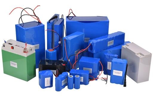
custom lithium battery packs collection


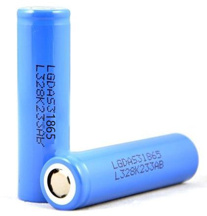 LG 18650 S3
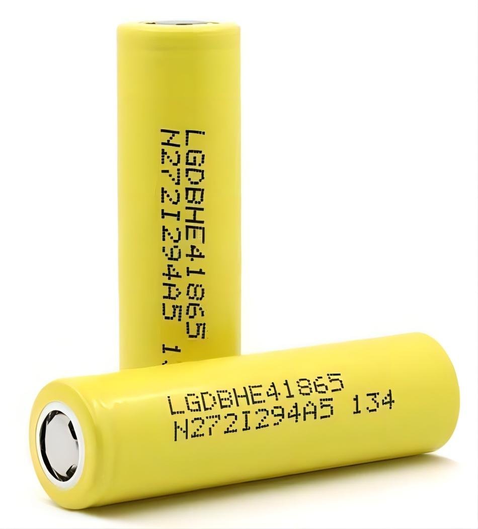 LG 18650 HE4
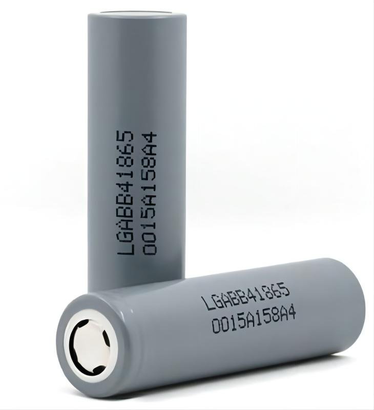 LG 18650 B4
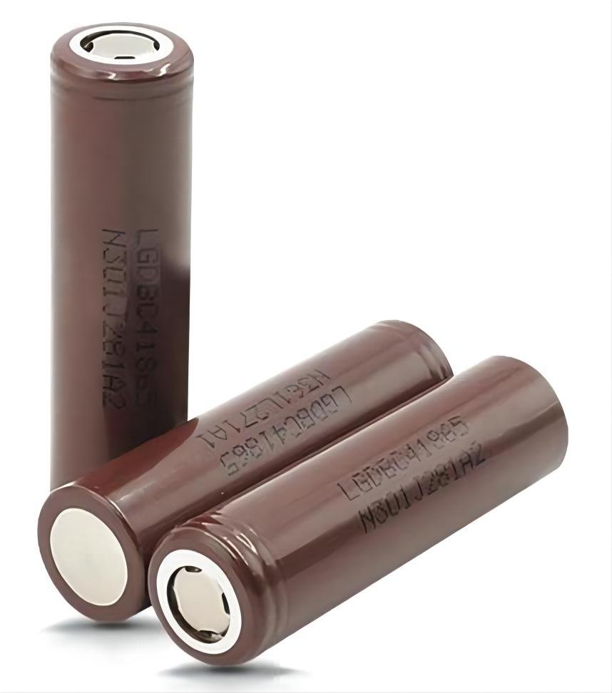
 LG INR18650 MJ1
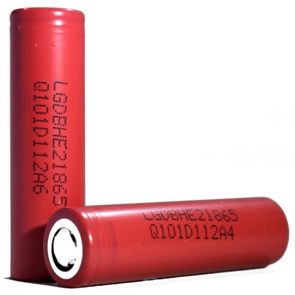 LG 18650 HE2
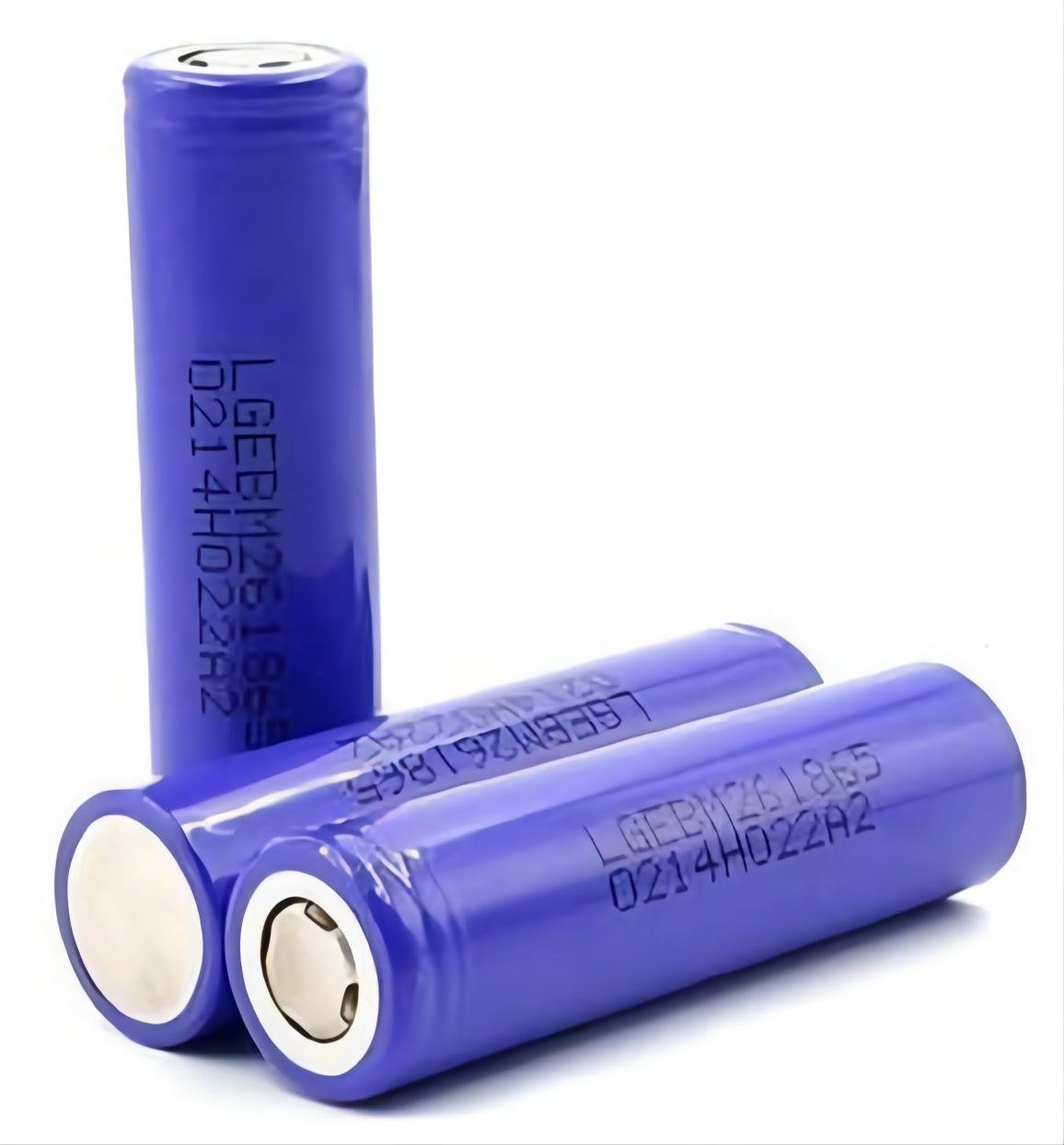 LG 18650 M26
 LG 18650 C4
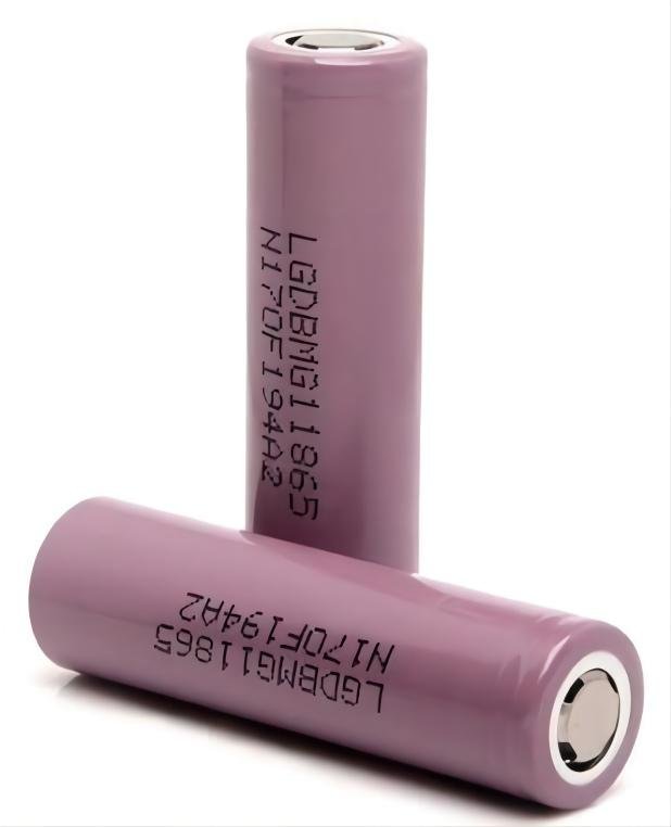 LG 18650 MG1
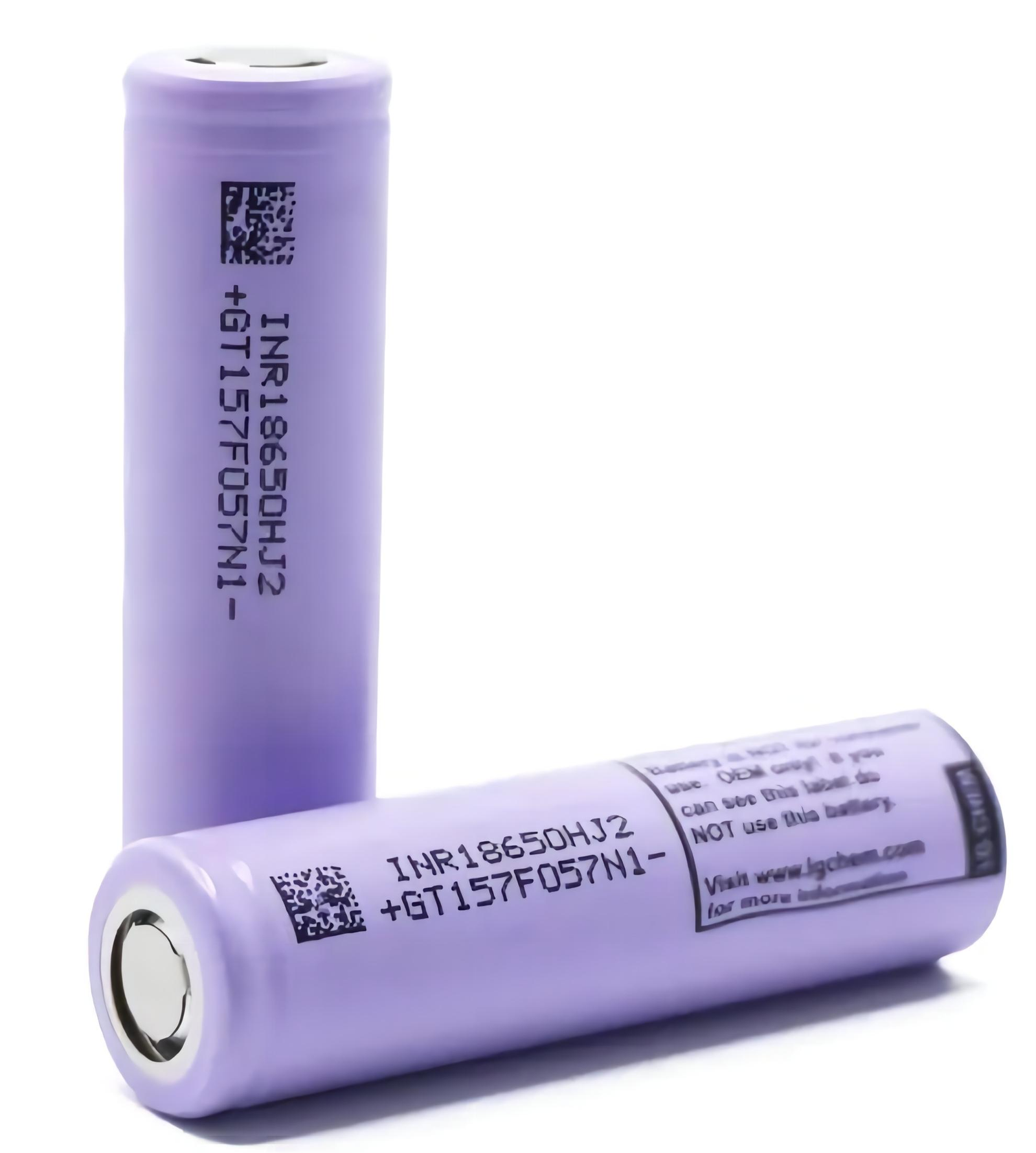 LG INR18650 HJ2
 LG 18650 MH1
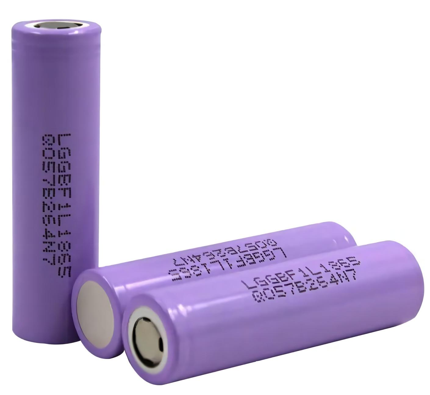 LG INR18650 F1L
 Sanyo UR18650 AY
 Panasonic UR18650 NSX
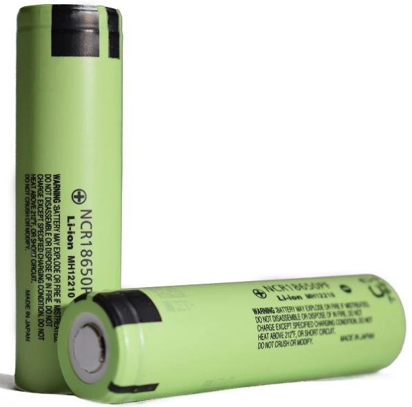 Panasonic UR18650 PF
 Panasonic NCR18650 A
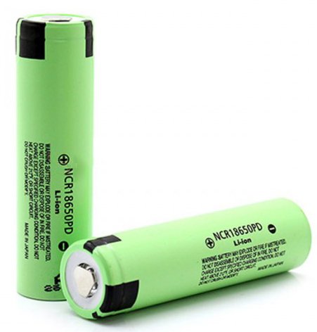 Panasonic NCR18650PD
 Panasonic NCR18650 BM
 Sanyo NCR18650 BL