18.2Wh LG-INR21700-M50LT Battery
LG-INR21700-M50LT
The LG-INR21700-M50LT model is one of the newer models on the market. It could be used in high-performance devices like E-scooter.
HIGHLIGHTS OF LG-INR21700-M50LT
- Nominal Voltage: 3.96V
- Nominal Energy: 18.2Wh
- Standard Constant Charging Current: 1,440mA
- Standard Constant Charging Voltage: 4.2V
- Standard Charging Cut-off Current:50mA
- Max. Charge Current: 3,360mA
MIND
Do not incinerate;
Do not disassemble;
Do not short positive and negative contacts;
Do not expose to heat;
Do not completely discharge;
Do not use force to install a li-ion battery;
Use only high quality battery charger;
Charge fully before first use;
Store in cold and dry place at approximately nominal voltage
APPEARANCE
There shall be no such defects as deep scratch, crack, rust, discoloration or leakage, which may adversely affect the commercial value of the cell.
Diameter : ≤ 21.44 mm
Diameter is defined as the largest data value measured on the “A” area of a cylindrical cell.
Height : ≤ 70.60 mm
TTS(Top to shoulder) : 0 +0.00/-0.55 mm
Weight: 68.2 ± 1.0g (TBD)

Nominal Specification of LG INR21700 m50LT
| Item | Condition | Specification |
| Energy* | By Std. charge/discharge | Nom. 18.2 Wh |
| Min. 17.6 Wh | ||
| Nominal Voltage | Average by Std. charge/discharge | 3.69V |
| Shipping Cell Voltage** | At ex-factory state. | 3.591 ± 0.01V |
| Standard charge | Constant current (1C=4800mA) | 0.3C (1,440mA) |
| Constant voltage | 4.20V | |
| End condition(Cut off) | 50mA | |
| Charging time | 4h | |
| Max. Charge Voltage | In all measurements and operations of the cell, the minimum allowable closed circuit voltage shall not exceed the following value | 4.20V |
| Max. Charge Current (complete full charge) | 0 ~ 25ºC (Atmosphere) | 0.3C (1,440mA) |
| 25 ~ 45ºC (Atmosphere) | 0.7C (3,360mA) | |
| Standard Discharge | Constant current | 0.2C (960mA) |
| End voltage(Cut off) | 2.50V | |
| Min. Discharge Voltage | In all measurements and operations of the cell, the minimum allowable closed circuit voltage shall not be below the following value | 2.50V |
| Max. Discharge Current | -20 ~ 10ºC | 0.5C (2,400mA) |
| 10 ~ 25ºC | 3.0C (14,400mA) | |
| 25 ~ 55ºC | 1.5C (7,200mA) | |
| Over Voltage Protection | Cell voltage shall not exceed the following value to prevent any safety events. And cell performance can’t be guaranteed between 4.20V and 4.25V | 4.25V |
| Under Voltage Protection | Cell voltage shall not drop below the following value to prevent any safety events. And cell performance can’t be guaranteed between 2.50V and 2.00V | 2.00V |
| Weight | With Tube and Washer | 68.2 ± 1.0g (TBD) |
| Operating Temperature(Atmosphere or Chamber Temperature) | Charge | 0 ~ 45ºC |
| Discharge | -20 ~ 55ºC | |
| Max. cell surface temperature should be below 70℃ for discharging.(Temperature cut-off function is needed on BMU under 70℃of cell surface temperature.) | ||
| Storage Temperature(for shipping state) | 1 month | -20 ~ 55ºC |
| 3 month | -20 ~ 45ºC | |
| 1 year | -20 ~ 25ºC | |
| Recovery capacity after the storage ≥ 80% of minimum energy(or capacity) | ||
| Storage Temperature (for full charged state) | 1 month | -20~ 45 ºC |
| 6 month | -20~ 25 ºC | |
| Recovery capacity after the storage ≥ 80% of minimum energy(or capacity) | ||
| Storage Humidity | - | Under 60% |
Performance Specification
Test condition
4.1.1 Standard Charge
Unless otherwise specified, “Rated Charge” shall consist of charging at constant current of 0.3C(1440mA).The cell shall then be charged at constant voltage of 4.20V while tapering the charge current. Charging shall be terminated when the charging current has tapered to 50mA. For test purposes, charging shall be performed at 25ºC.
4.1.2 Standard Discharge
“Standard Discharge” shall consist of discharging at a constant current of 0.2C(960mA) to 2.50V. Discharging is to be performed at 25ºC unless otherwise noted (such as capacity versus temperature).
4.1.3 Charge / discharge condition
Cells shall be charged at constant current of 0.3C(1,440mA) to 4.10V with end current of 1/20C. Cells shall be discharged at constant current of 0.5C(2,400mA) to 2.85V. Charging and discharging are to be performed at 25 ºC unless otherwise noted (such as capacity versus temperature). Cells are to rest 10 minutes after charge and 20 minutes after discharge at 25ºC.
Electrical Specification
| Item | Condition | Specification | |
| Storage Characteristics | Cells shall be charged per 4.1.1 and stored in a temperature-controlled environment at 25ºC for 30 days. After storage, cells shall be discharged per 4.1.2 to obtain the remaining capacity*. | Energy remain rate≥ 90% of Whmin in 4.2.3 | |
| High Temperature Storage Test | Cells shall be charged per 4.1.1 and stored in a temperature-controlled environment at 55ºC for 1 week. After storage, cells shall be discharged per 4.1.2 and cycled per 4.1.1 and 4.1.2 for 3 cycles to obtain recovered capacity | No leakage, Energy recovery rate≥ 80% of Whmin in 4.2.3 | |
| Temperature Dependency of Energy | Cells shall be charged per 4.1.1 at 25ºC and discharged per 4.1.2 at the following temperatures. | - | |
| Charge | Discharge | Energy | |
| 25ºC | -10ºC | ≥70% of Whmin in 4.2.3 | |
| 0ºC | ≥80% of Whmin in 4.2.3 | ||
| 25ºC | ≥100% of Whmin in 4.2.3 | ||
| 55ºC | ≥95% of Whmin in 4.2.3 | ||
Prohibitions
Do not connect battery directly to cigarette/aux jack in automobiles. Use only approved chargers.
Do not charge with constant current more than maximum charge current.
Do not charge the cell, which was discharged equal to 1V or under.
Do not disassemble or reconstruct the battery.
Do not throw or cause impact.
Do not pierce a hole in the battery with sharp things. (such as nail, knife, pencil, drill)
Do not use with other batteries or cells.
Do not solder on battery directly.
Do not press the battery with overload in manufacturing process, especially ultrasonic welding.
Do not use old and new cells together for packing.
Do not expose the battery to high heat. (such as fire)
Do not put the battery into a microwave or high pressure container.
Do not use the battery reversed.
Do not connect positive(+) and negative(-) with conductive materials (such as metal, wire)
Do not allow the battery to be immerged in or wetted with water or sea-water.
Do not give immoderate heat and force to battery cell during a welding process of metal plates on it.
How to Custom 21700 Battery Pack
We have the unique ability to develop custom 21700 battery pack to fit your needs. Our expert team of chemists, engineers, and manufacturers who use proven chemistry and production methods that will get from spec to production fast. Slim, flexible, more powerful.
WHAT WE CUSTOM
WHY CHOOSE US
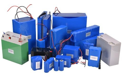
custom lithium battery packs collection







 LG 18650 S3
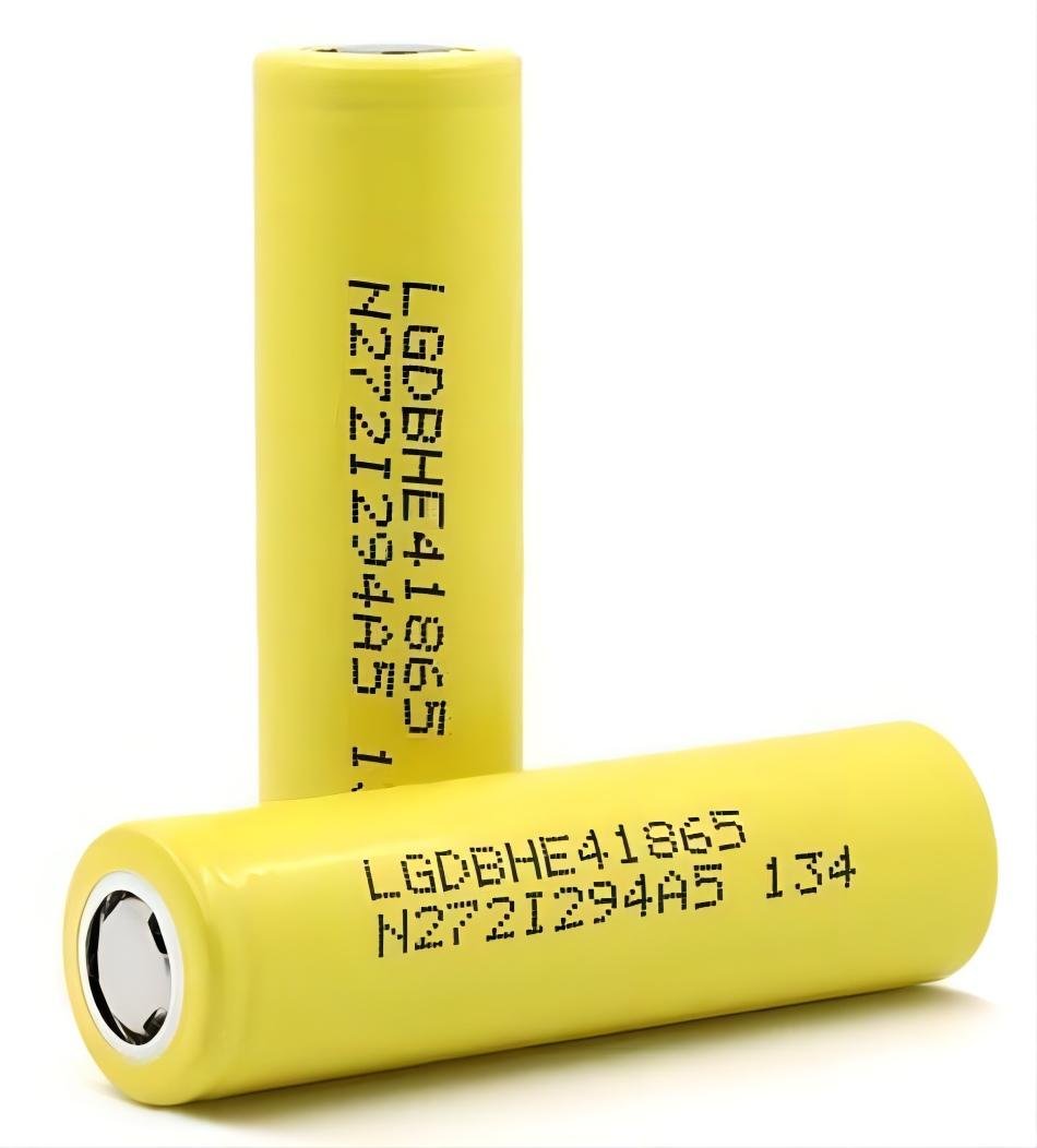 LG 18650 HE4
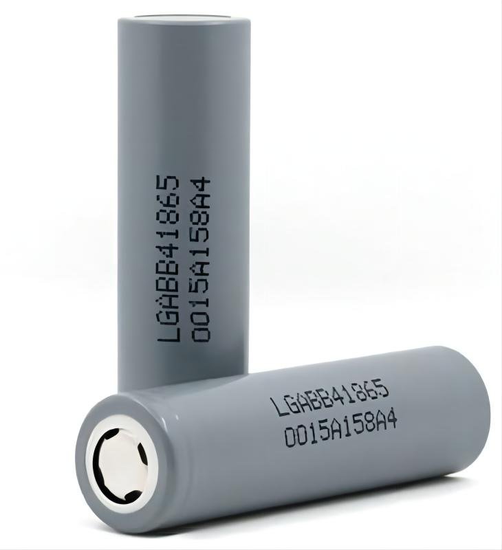 LG 18650 B4
 LG INR18650 MJ1
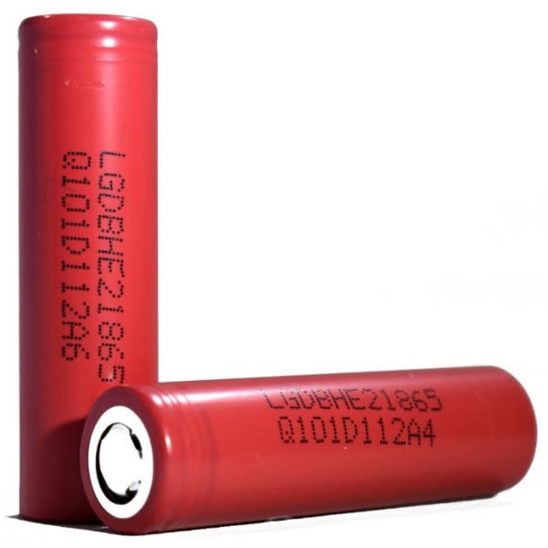 LG 18650 HE2
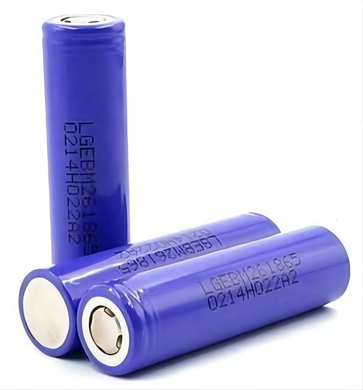 LG 18650 M26
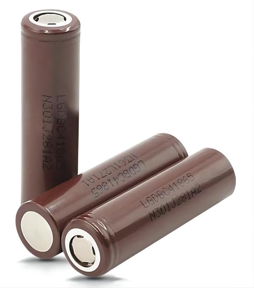 LG 18650 C4
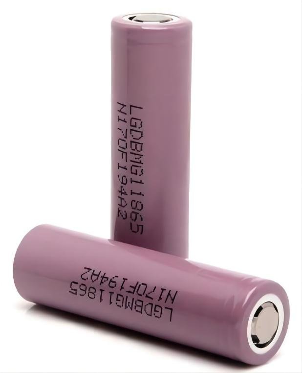 LG 18650 MG1
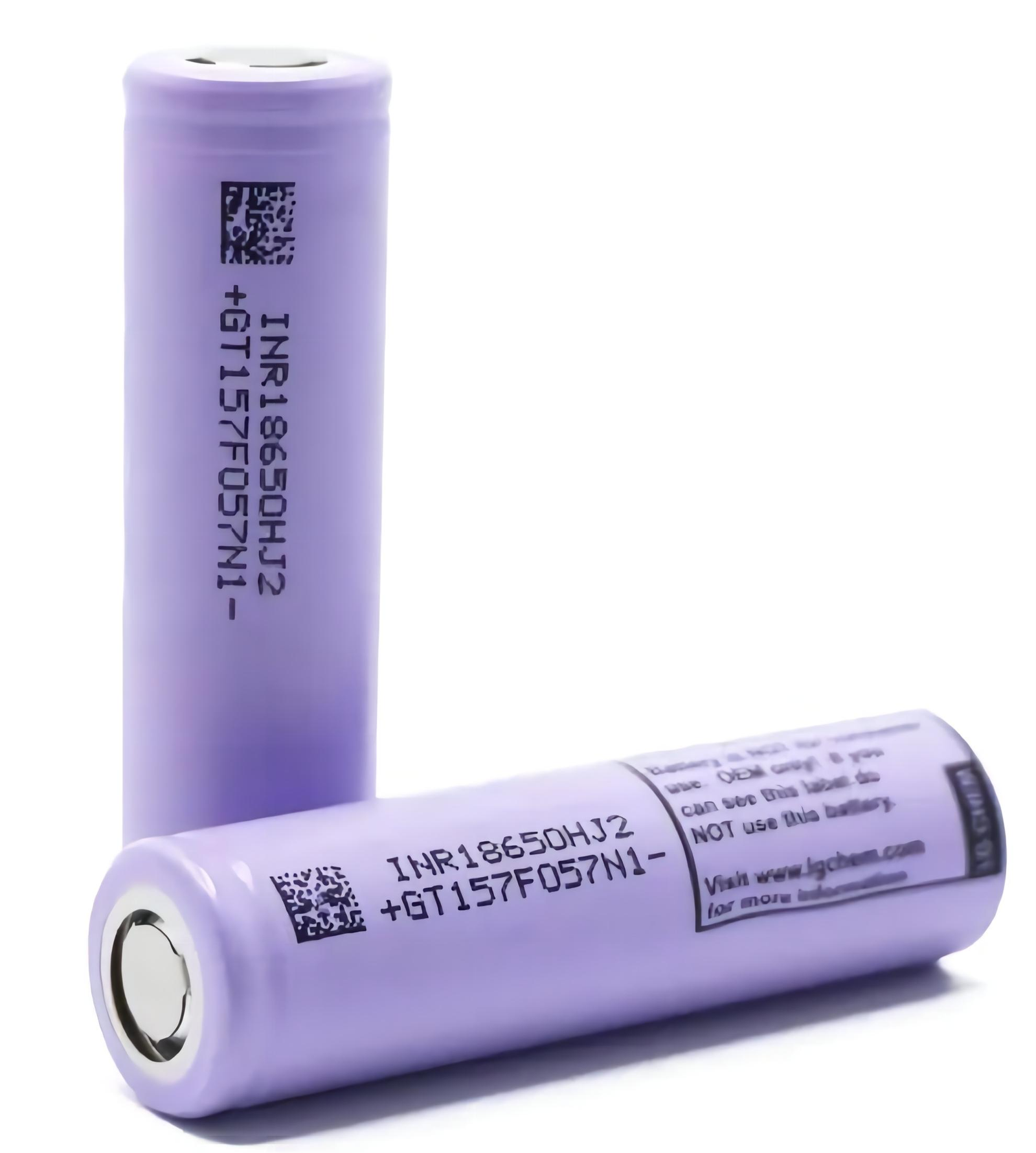 LG INR18650 HJ2
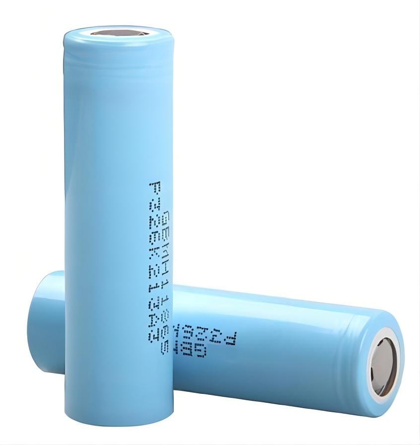 LG 18650 MH1
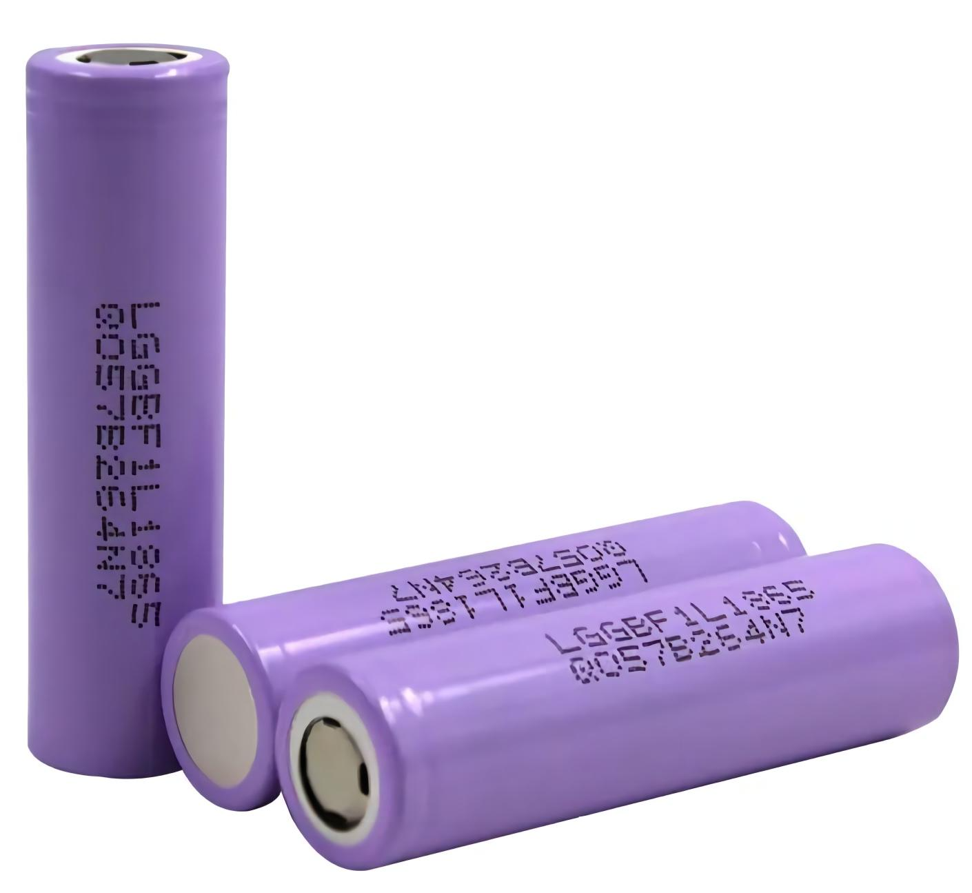 LG INR18650 F1L
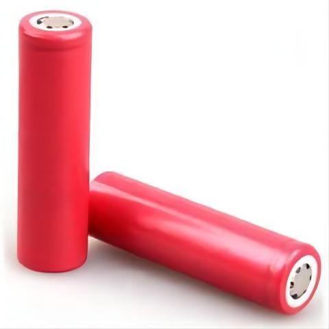 Sanyo UR18650 AY
 Panasonic UR18650 NSX
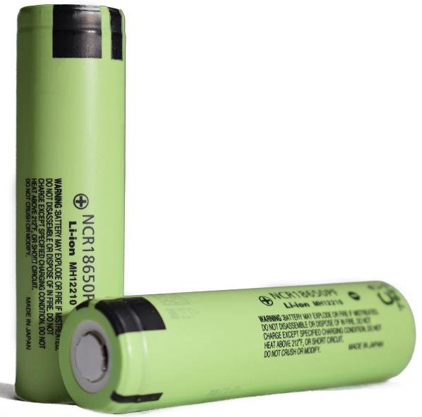 Panasonic UR18650 PF
 Panasonic NCR18650 A
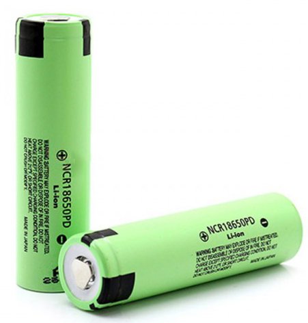 Panasonic NCR18650PD
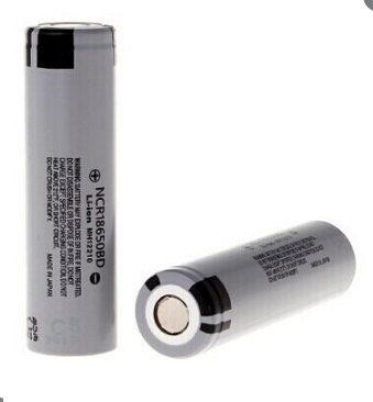
 Panasonic NCR18650 BM
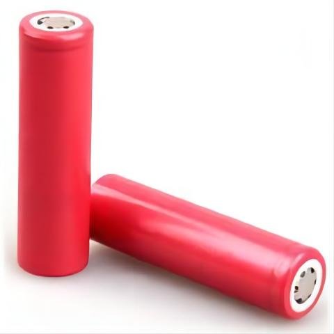 Sanyo NCR18650 BL