
Basics on Classifications of Battery Management System(BMS)
BMS is the abbreviation of battery management system. Basically, a power supply system composed of more than two single batteries requires a BMS.
Battery Monitoring
- measure battery and pack voltage
- measure battery and pack temperature
- measure battery and pack current
- measure internal resistance
- monitor coolant flow
Battery Status Estimation
- evaluate accurate State of Charge (SOC)
- evaluate accurate State of Health(SOH)
- evaluate Depth of Discharge(DOD)
- evaluate residual capacity


Battery Management
- manage hundreds battery modules in series or parallel
- protect single cell
- avoide battery thermal runaway
- battery balance
External Communication
- feedback status of battery to users by CAN bus
- Remote monitoring
Lithium Battery Design Design Ebook Download(2M, 20 pages, PDF)
Types of BMS
When it comes to classification, the first thing to mention is the classification criteria of BMS, which are classified by function and its topology. Here I will introduce you from two aspects.

CLASSSIFIED BY FUNCTION
TYPES OF BMS
1.Contant current/constant voltage (CCCV) chargers
2.Regulators
3.Meters
4.Monitors
5.Balancers
6.Protectors
1.Constant current and constant voltage charger (CCCV charger)
It can’t even be called a battery management system. Some simple chargers use CCCV charging to provide a constant current or voltage. CCCV charger is firstly used in battery cars that use lead-acid batteries in many areas. However, because lead-acid batteries are relatively sate, thus CCCV charger will not provide any protection.
CC:When first charging a pack, they produce a fixed constant current and allow the pack voltage to rise as it is charged.
CV: When the pack is nearly full, and its voltage reaches the constant voltage, the charger maintains that voltage and the pack current decays exponentially as the pack gets a finishing charge until the pack is full.
But we know from the previous introduction that this cannot provide any protection for the battery at all, but if it is not used with other control strategies, then this is equivalent to directly exposing the battery to an unprotected environment, which is more dangerous. The suitable current value will provide a balance between charging performance and battery safety.
Compared with lead-acid batteries, lithium ions batteries is more suitable for CCCV charging method. In addition, Li-ion batteries require a much longer CC mode.The CC-CV charging method is more efficient than either the CC or CV methods individually.

ADVANTAGES:
1.high capacity utilization
2.stable terminal voltage
DISADVANTAGES:
1.have chanllenge to balance charging speed,energy loss and temperature
2.cannot provide any protection for the lithium ions battery at all if there is no extra protection.
2.Regulator
A regulator is a shunt placed across a cell to bypass some or all of the charging current when the cell is fully charged.
That is , Regulator is a device that creates a low resistance path for current, then current can pass the circuit following a different path.
The simplest form.
It is basically equivalent to simply monitoring the voltage. When the voltage reaches the set value, the diode breaks down in reverse, dividing most of the current, which serves the purpose of protecting the battery.

Regulator is always used in
- defective devices bypass
- electrical noise bypass
- short circuit
- electronic filter circuit
- photo-voltagic
- lightning arrestor
Advantages:
- balance a Li-ion battery PACK
- Inexpensive
- Easy to understand
Limitation
1.Limited ability to handle current
When the current is greater than the upper limit of the shunt, there will still be current flowing through the battery. The BMS with a shunt will achieve better results,if there is a matched charger. Because the matched charger will dynamically adjust voltage.
In all, all the regulators can do is balance a pack. Use of regulators alone is not sufficient as a BMS because:
It does not prevent overcharging of individual cells. 2. It does not prevent overdischarging of cells. Even when used in combination with a matched charger, use of regulators is not sufficient as a BMS because it does not prevent over-discharging of cells.
3.Meters:
What is a Meter?
Meters simply measures parameters but do not actively control charging or discharging.
Functions:
1.Measure voltage of each cell 2.Measure pack current and temperature
3.Compile data 4.Estimate pack status: SOC, SOH
5.Report estimated status 6.Warn users of abnormal conditions
Limitation:
It relay on users because it is an integral part of BMS system. If users do not need this function, the system is useless. When a user leaves and lets the pack keep on charging, the pack has possibility to be damaged from overcharging.
Although a Meter seems to have so many functions, it is not sufficient as a BMS because Meters can not prevent individual cells from overcharging and it does not balance the pack.
4.Monitors
In fact, the control action is added to a meter, which forms a closed loop in the whole device. It can work automatically and perform corresponding actions based on the monitored data, such as using the relay action to cut off the charger or load. It can be done to protect the battery from overcharging, so as to ensure the safety of the battery.

However, its disadvantage is that it cannot balance the power between the single batteries.
5.Balancers
A balancer may be physically separated from the batteries, or mounted directly on the cells, or some combination within that range, and may use various balancing technologies, some more effective than others. A balancer adds the function of single battery equalization on the basis of the monitor, which can realize active and passive equalization, thereby ensuring the optimal use of the battery.
In summary, a balancer is sufficient as a BMS as long as it is wired in a way that allows it to control the charging source and the discharging load.
6.Protectors
A protector is like a balancer, except that it includes a switch to turn off the pack current.
A protector is usually an integral part of a battery, physically located inside the same enclosure, leaving only two power terminals coming out of its enclosure.

A protector is the industry standard solution for small batteries for consumer products, but it is rarely used in professional, large Li-Ion packs, because its switch is not likely to be able to handle high-power loads. For large packs, a balancer is usually chosen instead.
The switch in a protector is usually a solid-state type (transistors), able to handle 5A to 50A, and on the order of 50V in both the charging and discharging directions (this requires two sets of transistors in series, one for each direction of the pack current). This power level is usually sufficient just for small batteries.
In summary, a protector is completely sufficient as a BMS for smaller batteries.
Comparision of BMS function
| CCCV charger | regulator | meter | monitor | balancer | protector | |
|---|---|---|---|---|---|---|
| Measure | Yes | Yes | Yes | (Yes) | ||
| Compute | (Yes) | (Yes) | (Yes) | (Yes) | ||
| Report | Yes | Yes | (Yes) | (Yes) | ||
| Balance | Yes | Yes | Yes | |||
| Charge protect | Yes | Yes | Yes | |||
| Discharge protect | Yes | Yes | Yes | Yes |
Lithium Battery Design Design Ebook Download(2M, 20 pages, PDF)
CLASSSIFIED BY TOPOLOGY
1. Centralized BMS
A centralized BMS encapsulate the entire BMS in one device, leaving a wire to connect to the conductor battery.

2. Modular BMS
It is very similar to a centralized BMS, but a modular BMS is divided into many identical sub-modules. The wires of each package are connected to different parts of the entire battery panel to monitor a certain area. We say it is a module with the same function, but in fact, there will be a module assigned as the main module, which is used to manage and schedule the entire battery pack and is responsible for communicating with the outside world. Other slave BMS communicate with the main BMS through the communication bus, but the functions between them are the same.
Disadvantages
- The first is the need to add additional wires. Compared with centralized, modular stepping needs to be connected to the battery pack, and wires are also required between each module.
- The cost is higher. The main reason is that the functions of each module are the same, but not all functions will be used, which creates waste, especially the slave modules, which do not have many functions.

Advantages:
- Easy maintenance
- cheap prices
First of all, because it is equivalent to miniaturizing a centralized BMS and cascading multiple times, it has most of the advantages of centralized, such as easy maintenance, cheap prices, etc.
- Avoiding the hidden dangers and errors caused by too long wires
- Secondly, due to the small size of a single module, the wire from the sub-module to the single battery will be relatively short and can be closer to the battery.
- It is also easy to expand. Because this BMS can add more sub-modules to achieve expansion.
3.Master-slave BMS
A master-slave BMS is an improved version of modular BMS. It is similar to a modular system.
We separate the modules according to the different master-slave functions, and remove the functions that are not used by the slave modules.

Advantages:
- Reduce a lot of costs.
The main BMS is responsible for relatively many functions, including calculation, prediction, decision-making, communication, etc.
- The slave unit is basically only responsible for measurement.
In this way, it can be said to inherit most of the advantages of the modular structure, while also reducing the cost of expansion.
4. Distributed BMS
In the previous different BMS, various electronic devices will not be installed on a single battery, and they are basically measured by wires in the past. However, in a distributed system, our measurement unit and other electronic equipment are directly installed in a circuit board integrated with the single battery.
The advantage of this is that compared with the previous few, the connection between the BMS and the single battery is basically eliminated. Then it is a bit like the master-slave model in that it will also have a controller responsible for computing, forecasting, decision-making, etc. Communication between modules is based on bus.
Advantages:
- The first is to have extremely high expandability, which can be refined to the expansion of a single battery.
- The second is that the connection reliability is high, there are basically no cables that are too long, and the battery and the measurement circuit are closely combined, which also reduces interference and errors. The security is also very high.
- It is also easy to maintain. If it is broken, only a small unit needs to be replaced.
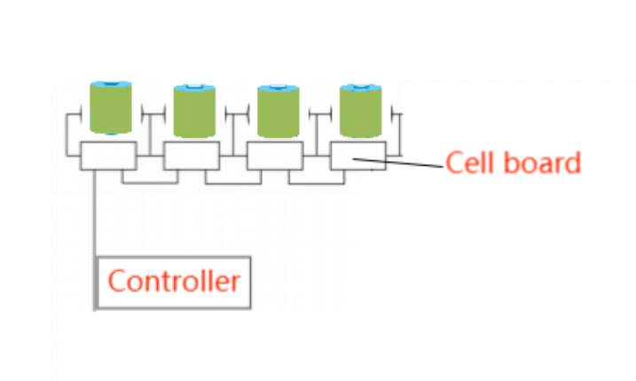
Disadvantages:
- The first is that the cost is very high, because each monomer adds a set of equipment, so the overall cost is very high.
- The second is that the volume is too large. This is also well understood. There is a measurement system next to each cell of each battery, which will affect the volume of the entire battery panel.
Comparison of BMS Topologies
| Measurement Quality | Noise Immunity | Versatility | Safety | Electronics Cost | Assembly Cost | Maintenance Cost | |
|---|---|---|---|---|---|---|---|
| Centralized | better | Best | Good | Good | Good | better | Good |
| Master-Slave | better | Best | better | Good | Best | better | Good |
| Modular | better | Best | better | Good | Best | better | Good |
| Distributed | Best | better | Best | Best | Best | Good | better |
Lithium Battery Design Design Ebook Download(2M, 20 pages, PDF)
Prev Article: What is Lithium Battery C-rate and How to Calculate it?
Next Article: Lithium Battery Performance and Quality Tests



Leave A Comment